

Hydrogen Compressors for Sale | Reciprocating compressor | Piston-type booster compressor
Hydrogen Compressors for Sale | Reciprocating compressor | Piston-type booster compressor
Unique advantages :
A. Modular 4 or 6 cylinder design;
B. Up to 5-stage compression;
C. Hermetically gas-tight magnetic coupling drive;
D. Water-cooling system with individual cylinder/ inter-stage cooling;
E. Ex-proof versions acc. to ISO.
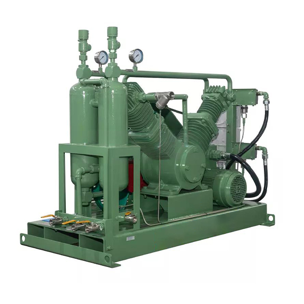
Working Principle
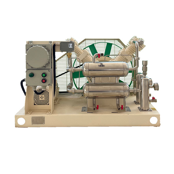
The compressor is a reciprocating, piston-type (with middle body and crosshead), single-acting, air-cooled, and fully oil-free lubrication compressor.
The compressor is composed of a main unit, a motor, a support (with buffer tank), and electrical control components. Both the main unit and the motor are placed on the support of the buffer tank. The two buffer tanks are the intake buffer and the exhaust buffer respectively, and both are equipped with gas pressure display devices, check valves, and intake and exhaust ball valves. Solenoid valves are installed in both the intake pipeline and the unloading pipeline.
When the compressor is working, the motor drives the crankshaft to produce rotational motion through V-belt transmission, and the connecting rod drives the piston to produce reciprocating motion, which changes the cylinder volume and thus the gas pressure in the cylinder. The gas under pressure is sucked into the cylinder through the intake buffer tank, intake solenoid valve, intake pipe, and intake valve, compressed into compressed gas with the required pressure through one-stage, two-stage or three-stage compression, injected into the exhaust buffer tank through the check valve and pipeline, and then enters the air storage tank through the pipeline for use.
When the intake and exhaust compression ratio is small, it is one-stage compression; when it is large, it is two-stage or three-stage compression with an intercooler.
Application Scope of the Compressor
It is used to boost the pressure of dry and particle-free oxygen, nitrogen, air, and other non-toxic and non-explosive gases.
Installation
The compressor should be placed in a dry and well-ventilated room with an ambient temperature between -20℃ and 40℃. There should be enough space around it to facilitate maintenance and service work.
Pay attention to the voltage, frequency, etc. of each electrical component, and wire according to Section 7, Electrical Schematic Diagram.
The installed intake and exhaust pipelines should avoid rigid connection.
There is no need to specially make a foundation; just level the ground and fix the foundation bolts with expansion bolts.
Compressors with pneumatic angle valve series: If the system intake pressure is < 0.7MPa, an additional air source with pressure ≥ 0.7MPa is required to open the pneumatic angle valve, and the air source should be connected to the reserved interface of the two-position three-way solenoid valve; if the system intake pressure is ≥ 0.7MPa, no additional air source is needed.
Installation and Use
After the compressor is installed and confirmed to meet the requirements, it can be commissioned.
Before commissioning, check: whether the bolts and nuts are loose. Press the middle part of the V-belt with the index finger to check the V-belt; it is normal if the V-belt can sag about 10mm.
Instantly start, connect the intake pipe, open the intake and exhaust ball valves, and turn on the power. When the intake pressure reaches the set upper intake pressure limit, the compressor starts. Check whether the rotation direction is the same as the arrow shown on the compressor.
If the above inspections are normal, let the compressor run under low load for more than 10 minutes.
Commissioning: For compressors without pneumatic angle valve series, operate according to 2.4.1; for compressors with pneumatic angle valve series, operate according to 2.4.2.
Supplementary Operation Instructions
Close the exhaust ball valve; the gas pressure inside the air storage tank will rise. When the exhaust pressure rises to the set upper pressure limit, the intelligent pressure controller acts, the pneumatic angle valve closes, and the compressor enters the idling state. After maintaining this state for approximately 5 minutes (this time is adjustable), if the pressure of the exhaust buffer tank is still higher than the set lower exhaust pressure limit, the time delay relay acts to cut off the power supply of the contactor circuit, the motor stops rotating, the pressure inside the air storage tank will no longer rise, and the unloading solenoid valve opens to connect the exhaust chamber and pipeline with the suction chamber and pipeline. This is to realize no-load startup when restarting the compressor again.
Open the exhaust ball valve; the gas pressure inside the air storage tank will drop. When the exhaust pressure drops to the set lower exhaust pressure limit and the intake pressure reaches the set upper intake pressure limit at the same time, the pressure controller is powered on, the compressor resumes startup, the unloading valve closes, the intake solenoid valve opens, and the pressure continues to rise. At this time, the compressor is working normally.
If the above inspections are normal, the compressor can start working. Note during operation: It is strictly prohibited to set the exhaust pressure to exceed the maximum rated pressure value; otherwise, faults will be caused. When the work is completed or the power is cut off, the power supply should be turned off.
※ If the intake pressure is not controlled, the compressor is only controlled by the set upper and lower limits of the exhaust pressure.